When learning to fly, one of the first things that student pilots learn about is the phenomenon known as asymmetrical propeller loading, or p-factor. In aircraft with propellers, p-factor causes a yawing moment when the aircraft is at high angles of attack. For most single engine aircraft, this means that the aircraft will yaw to the left at high angles of attack unless an appropriate right rudder correction is applied. (This result applies to propellers which rotate clockwise as viewed from behind. For propellers that rotate counterclockwise, the yaw is to the right at high angles of attack.)
Wikipedia gives the standard explanation:
When an aircraft is in straight and level flight at cruise speed, the propeller disc will be normal (i. e. perpendicular) to the airflow vector. As airspeed decreases and wing angle of attack increases, the engines will begin to point up and airflow will meet the propeller disc at an increasing angle, such that horizontal propeller blades moving down will have a greater angle of attack and relative wind velocity and therefore increased thrust, while horizontal blades moving up will have a reduced angle of attack and relative wind velocity and therefore decreased thrust. Vertical blades are not affected. This asymmetry in thrust displaces the center of thrust of the propeller disc towards the blade with increased thrust, as if the engine had moved in or out along the wing.
That is, the effect is chiefly caused by an increase in the angle of attack of the downward moving propeller. Let’s call this the angle-of-attack effect.
The Pilot’s Handbook of Aeronautical Knowledge is a bit confusing on this issue. In the section on p-factor, the first paragraph seems consistent with the Wikipedia explanation, saying that the “bite” of the downward-moving blade is greater than the “bite” of the upward-moving blade, which is consistent with the idea that p-factor is caused by a change in the angles of attack of the downward and upward moving blades. However, the Handbook goes on to say,
This asymmetric loading is caused by the resultant velocity, which is generated by the combination of the velocity of the propeller blade in its plane of rotation and the velocity of the air passing horizontally through the propeller disc. With the aircraft being flown at positive AOAs, the right (viewed from the rear) or downswinging blade, is passing through an area of resultant velocity which is greater than that affecting the left or upswinging blade. Since the propeller blade is an airfoil, increased velocity means increased lift. The downswinging blade has more lift and tends to pull (yaw) the aircraft’s nose to the left.
That is, the effect is chiefly caused by the increase in the relative velocity of the downward moving blade, which is actually inconsistent with the angle of attack, or “bite” explanation. Let’s call this the velocity effect.
Austin Meyer, the owner and developer of X-Plane, has an interesting aviation blog, called Austin’s Adventures. In a recent post, A Few Myths Austin Wants to Bust, he argues that what most pilots believe ( that p-factor is caused by the angle of attack) is incorrect:
So why DOES the plane pull left in a climb even though the descending blade is NOT at a higher angle of attack? Look to helicopters for the answer. Their ADVANCING blade (the main rotor blade that is coming FORWARD) wants to put out a LOT more lift since it is moving at it’s rotational speed PLUS the speed of the aircraft.
So what causes p-factor, the angle-of-attack effect or the velocity effect? To find out, I’m going to use some ideas common to the analysis of rotor systems in aeronautics. I was actually quite surprised by the result! Because what follows is fairly technical, I’ll spill the beans and reveal the answer now: Both results are about equally important.
The Analysis. How should we do the analysis? A complete analysis, using CFD (computational fluid dynamics) or blade element theory is not really necessary. Instead, we can use a simplified analysis called typical section analysis that gets the answer mostly right. For our analysis, it should certainly tell which effect is most important. The idea in typical section analysis is that we don’t analyze the entire propeller blade; instead, we analyze a “typical section” that stands in for the whole blade. Think of the typical section as representing the average blade behavior. The typical section is really a specific section of the blade, at a specfiic radius.
What is the right radius to analyze? The simplest analysis would suggest that we use the section at 50% of the propellor rotor radius — 50% is the average radius, after all! But that’s not right, since there’s more rotor area outside the 50% radius than inside. In fact, there’s three times as much! So the typical section radius ought to be greater than 50%. If we only cared about area, we would take the typical section radius to be 70.7% of the rotor radius, since that results in exactly half of the area inside and half outside the typical section. But the blades are more effective at greater radius, since they are moving faster there, so the typical section should be even further out. We’ll do the typical section analysis at the 75% radius.
Next, we have to understand what the typical section “sees” aerodynamically, that is, what is the relative wind at the typical section. To do that, we draw a so-called velocity triangle, which shows the contributions to the relative velocity from two sources: the motion of the aircraft relative to the air mass, and the motion of the typical section relative to the airframe. The velocity triangle for the downward traveling blade is shown below:

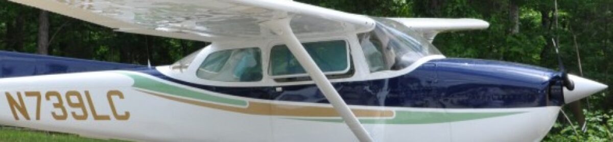
To make this velocity triangle, I used book numbers from my own airplane, a Cessna 172RG. The propeller diameter is 76.5 inches. In a max power climb configuration (the worst-case p-factor), the engine speed is 2700 RPM. That means the typical section has a velocity due to rotation of
(1) 
(As a check, note that the tip Mach number  , which is about right). The velocity due to aircraft velocity is easier. In an 84 kt
  climb, it is simply
![\[V_{ac}=84\text{ kt}\times \dfrac{1.6878\text{ ft/s}}{1\text{ kt}}=141.78\text{ ft/s}\]](http://flyingprofessors.net/wp-content/ql-cache/quicklatex.com-fe6f83656b607a4086c2f13b4fda24a1_l3.png "Rendered by QuickLaTeX.com")
The magnitude of  is given by
![\[V_\text{rel}=\sqrt{V_r^2+V_\text{ac}^2}=690.6\text{ ft/s}\]](http://flyingprofessors.net/wp-content/ql-cache/quicklatex.com-5a256ffa818b03d46d663cede76691be_l3.png "Rendered by QuickLaTeX.com")
Now what happens if the angle of attack of the aircraft is increased by, say, 5 deg? The lengths of  and
and  don’t change, but is tilted up 5 deg, resulting in the following velocity triangle:

The geometry is a little harder now, since the triangle is no longer a right triangle. I’ll just give the important results, without showing the math. Specifically, for this new triangle,
![\[V_\text{rel}=702.6\text{ ft/s}\]](http://flyingprofessors.net/wp-content/ql-cache/quicklatex.com-431c72477e551fe0afe273bad776b4fe_l3.png "Rendered by QuickLaTeX.com")
so that indeed the relative velocity does increase, by about 1.74%. In addition, although it’s not that clear from the figures, the angle of attack of the blade increases by  .
.
So both effects discussed at the beginning of this post do exist. Which is more important? We need to estimate the change in lift. For the first effect (change in magnitude of  , use the fact that lift at constant angle of attack is proportional to velocity squared. The sectional lift is
![\[\ell=\frac{1}{2}\rho V_\text{rel}^2 c_\ell c\]](http://flyingprofessors.net/wp-content/ql-cache/quicklatex.com-30cab1b05248ad0b2c6a5942d86ce03c_l3.png "Rendered by QuickLaTeX.com")
where  is the air density,
  is the sectional lift coefficient, and
  is the blade chord. So for small changes in relative velocity, the change in lift is
![\[\Delta\ell=\rho V_\text{rel}\Delta{}V_\text{rel}{}c_\ell c\]](http://flyingprofessors.net/wp-content/ql-cache/quicklatex.com-95258cf6f6f826636bd816e31c466066_l3.png "Rendered by QuickLaTeX.com")
The change in lift due to change in angle of attack is
![\[\Delta\ell=\frac{1}{2}\rho{}V_\text{rel}^2c_{\ell_\alpha}c\Delta\alpha\]](http://flyingprofessors.net/wp-content/ql-cache/quicklatex.com-7c169377cef0916d0895c10560d04f5f_l3.png "Rendered by QuickLaTeX.com")
Now, the ratio of these two effects is
![\[R=\dfrac{\rho V_{\text{rel}}\Delta V_{\text{rel}}c_{\ell}c}{\frac{1}{2}\rho V_{\text{rel}}^{2}c_{\ell_{\alpha}}c\Delta\alpha}=\dfrac{2\Delta V_{\text{rel}}c_{\ell}}{V_{\text{rel}}c_{\ell_{\alpha}}\Delta\alpha}\]](http://flyingprofessors.net/wp-content/ql-cache/quicklatex.com-48156388330f674c46bf4276829fbb7a_l3.png "Rendered by QuickLaTeX.com")
If  is much bigger than one, the velocity effect dominates; if is much less than one, the angle of attack effect dominates.
So what is ? We already know for our example that  and
and  . For a well-designed propeller in a highly loaded condition (as in our climb example),
  . And for any airfoil,
![\[c_{\ell_\alpha}\approx2\pi\]](http://flyingprofessors.net/wp-content/ql-cache/quicklatex.com-8cfddee3af2f2fd61e675a7158f8e221_l3.png "Rendered by QuickLaTeX.com")
Putting all these results together, we have that
![\[R\approx1.29\]](http://flyingprofessors.net/wp-content/ql-cache/quicklatex.com-7219bbe2a280fc014c64f262d1952fb5_l3.png "Rendered by QuickLaTeX.com")
In other words, the two effects are almost exactly the same size. Both effects are needed to adequately explain p-factor!
Now, we actually don’t know very well, but we know that it is close to unity (probably within a factor of 2), but that doesn’t really detract from our result very much. The main point of this simplified analysis is that the two effects are roughly comparable in size. Any careful analysis of p-factor therefore must include both effects.